Understanding how materials respond to applied loads is one of the most fundamental responsibilities of a civil engineer. Whether designing a reinforced concrete beam, assessing the safety of a steel bridge, or evaluating soil deformation beneath a foundation, engineers rely on stress–strain relationships to predict how materials behave and when they may fail. This concept forms the backbone of subjects such as strength of materials, structural analysis, geotechnical engineering, and pavement design.
This article provides a detailed, academic explanation of stress–strain relationships, focusing on how civil engineers use them to analyze material behavior, ensure safety, and prevent structural failure.
1. What Are Stress and Strain?
Stress
Stress is the internal resisting force per unit area developed within a material when an external load is applied.σ=AP
Where:
- σ = stress (Pa or N/m²)
- P = applied load (N)
- A = cross-sectional area (m²)
Types of stress commonly encountered in civil engineering include:
- Normal stress (tension or compression)
- Shear stress
- Bending stress
- Torsional stress
Strain
Strain is the deformation of a material per unit original dimension.ε=LΔL
Where:
- ε = strain (dimensionless)
- ΔL = change in length
- L = original length
Strain indicates how much a material deforms under stress and is critical in assessing serviceability and failure.
2. The Stress–Strain Curve
A stress–strain curve is obtained from laboratory tests (usually tensile tests) and graphically represents material behavior under loading.
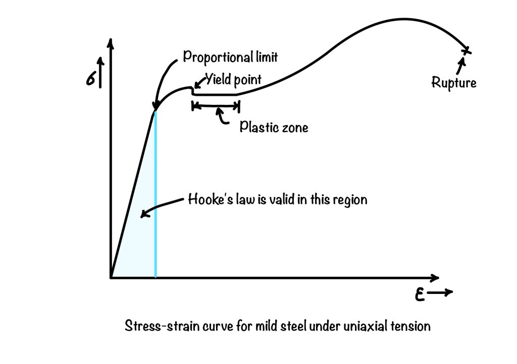
Typical Stress–Strain Curve for Ductile Materials (Steel)
Key regions include:
- Proportional Limit
Stress is directly proportional to strain (Hooke’s Law applies). - Elastic Region
Deformation is reversible. Removal of load restores the original shape. - Yield Point
Large strains occur with little or no increase in stress. - Plastic Region
Permanent deformation occurs. - Ultimate Stress
Maximum stress the material can withstand. - Fracture Point
Material failure occurs.
Understanding these regions allows engineers to design structures that operate safely within allowable limits.
3. Hooke’s Law and Elastic Behavior
Within the elastic range:σ=Eε
Where E is Young’s Modulus, a measure of material stiffness.
Typical values:
- Structural steel: ~200 GPa
- Concrete: 20–30 GPa
- Timber: 8–14 GPa
Engineering Significance
- Higher E → stiffer material → less deformation
- Used in deflection calculations, column buckling, and elastic analysis
Engineers ensure that working stresses remain within the elastic region to avoid permanent deformation.
4. Ductile vs Brittle Materials
Ductile Materials
- Exhibit large plastic deformation before failure
- Examples: steel, aluminum
- Failure is gradual and visible
Brittle Materials
- Fail suddenly with little plastic deformation
- Examples: concrete, glass, cast iron
This distinction is critical in civil engineering because ductile failure provides warning, while brittle failure can be catastrophic.
5. Stress–Strain Behavior of Common Civil Engineering Materials
Steel
- Linear elastic region
- Clear yield point
- High ductility
- Ideal for tension members
Concrete
- Nonlinear stress–strain curve
- Strong in compression, weak in tension
- Brittle behavior
- Requires reinforcement
Soil
- Highly nonlinear
- Stress–strain behavior depends on:
- Confining pressure
- Density
- Moisture content
These material-specific behaviors guide material selection and design methods.
6. Predicting Material Failure Using Stress–Strain Data
Failure Criteria
Civil engineers use stress–strain relationships to apply failure theories, such as:
- Maximum stress theory
- Maximum strain theory
- Mohr–Coulomb theory (for soils)
- Von Mises criterion (for ductile metals)
Each criterion helps predict whether a material will fail under complex loading conditions.
Factor of Safety
To account for uncertainties:Factor of Safety=Allowable Stress/Failure Stress
This ensures structures remain safe even with:
- Material imperfections
- Construction errors
- Unexpected loads
7. Application in Structural Design
Beam Design
- Stress–strain relations determine bending stress:
σ=IMy
Column Buckling
- Elastic modulus affects critical buckling load:
Pcr=(KL)2π2EI
Reinforced Concrete
- Compatibility of strain between steel and concrete ensures composite action
These calculations directly depend on accurate stress–strain modeling.
8. Laboratory Testing and Real-World Data
Engineers rely on:
- Tensile tests
- Compression tests
- Triaxial soil tests
- Unconfined compression tests
These experiments generate stress–strain curves used in:
- Design codes
- Finite element modeling
- Failure analysis
9. Limitations of Idealized Stress–Strain Models
While stress–strain curves are powerful tools, real-world materials:
- Exhibit time-dependent behavior (creep)
- Show temperature sensitivity
- Experience fatigue under cyclic loading
Advanced models incorporate nonlinearity and plasticity for more accurate predictions.
10. Why Stress–Strain Relationships Matter in Civil Engineering
Mastering stress–strain relationships allows engineers to:
- Predict material failure
- Prevent structural collapse
- Optimize material use
- Ensure safety and serviceability
Every major civil engineering discipline relies on this concept, making it a cornerstone of engineering education and practice.
Conclusion
Stress–strain relationships provide civil engineers with a scientific framework to understand how materials respond to loads and when they are likely to fail. By interpreting stress–strain curves, applying elastic theory, and using safety factors, engineers can design structures that are both efficient and safe. From classroom problem-solving to real-world structural design, this concept remains essential to responsible engineering practice.
No responses yet